

Basic Information
・Our products are suitable for a wide range of applications for civil and aerospace systems.
・The grade of the inspection method is classified into three types: standard, commercial, and custom.
・We conduct rigorous mechanical and electrical inspections on all lot samples, and visually inspect all products to ensure high quality and reliability.
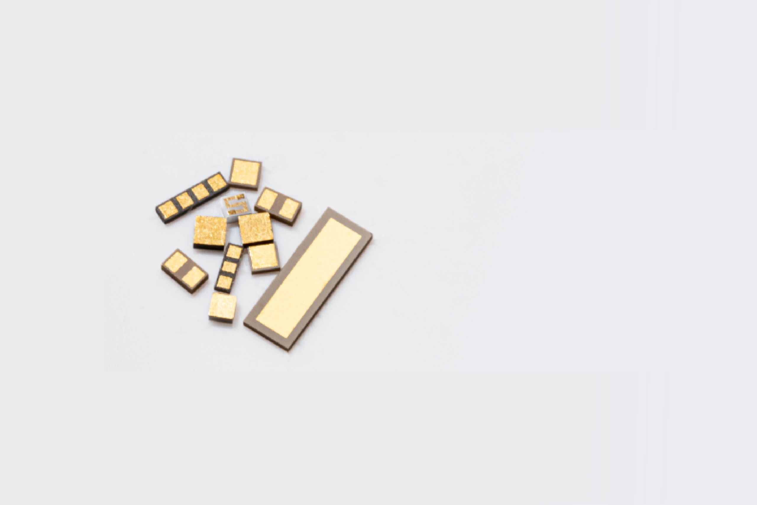
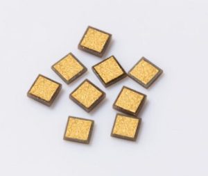
Single layer ceramic capacitor “A type” (Class Ⅰ, Class Ⅱ)
Single layer ceramic capacitor “B type” (Class Ⅰ, Class Ⅱ)
Single layer ceramic capacitor “C type” (Class Ⅰ, Class Ⅱ)
Rectangular single layer ceramic capacitor
Binary type ceramic capacitor
Gap type ceramic capacitor
| Inspection Item | Inspection Quantity | |
| Appearance | Visual Inspection | Inspection Lot AQL II(1.0%) |
| Electrical Properties | Capacitance | Inspection Lot AQL II(1.0%) |
| Dielectric Loss | Inspection Lot AQL II(1.0%) | |
| Insulation Resistance | 10 pcs per Wafer Lot . 0 Allowable Failures | |
| Mechanical Properties | Wire Pull Strength | 3 pcs per Wafer Lot . 0 Allowable Failures |
| Heat Resistant | 400 °C For 5 min | 5 pcs per Wafer Lot . 0 Allowable Failures |
| Size | Dimension Measurement | 3 pcs per Wafer Lot . 0 Allowable Failures |
Single layer ceramic capacitor “A type” (Class Ⅳ)
Single layer ceramic capacitor “C type” (Class Ⅳ)
Multi-electrode Ceramic Capacitor
| Inspection Item | Inspection Quantity | |
| Appearance | Visual Inspection | Inspection Lot AQL II(1.0%) |
| Electrical Properties | Capacitance | Inspection Lot AQL II(1.0%) |
| Dielectric Loss | Inspection Lot AQL II(1.0%) | |
| Insulation Resistance | Inspection Lot AQL I(0.15%) | |
| Mechanical Properties | Wire Pull Strength | 3 pcs per Wafer Lot . 0 Allowable Failures |
| Size | Dimension Measurement | 3 pcs per Wafer Lot . 0 Allowable Failures |
Integrated Resistor Capacitor
| Inspection | Inspection Quantity | Allowable number of Defects | |
| Visual Inspection | Inspection Lot AQL II (1.0%) | Inspection Lot AQL II(1.0%) | |
| Electrical Properties | Capacitance | Inspection Lot AQL II (1.0%) | Inspection Lot AQL II(1.0%) |
| Dielectric Loss | Inspection Lot AQL II (1.0%) | Inspection Lot AQL II(1.0%) | |
| Insulation Resistance | Inspection Lot AQL I(1.15%) | Inspection Lot AQL I(0.15%) | |
| Resistance Values | Inspection Lot AQL I( 1.5%) | Inspection Lot AQL I( 1.5%) | |
| Mechanical Properties | Wire Pull Strength | 3 pcs per Wafer Lot | 0 |
| Heat Resistance | 320 °C For 5 min. | 3 pcs per Wafer Lot | 0 |
| Size | Dimension Measurement | 3 pcs per Wafer Lot | 0 |
Thin Film Chip Resistor
| Inspection | Inspection Quantity | Allowable number of Defects | |
| Visual Inspection | Inspection Lot AQL II(1.0%) | Inspection Lot AQL II(1.0%) | |
| Electrical Properties | Resistance Values | Inspection Lot AQL I(1.5%) | Inspection Lot AQL I(1.5%) |
| Mechanical Properties | Wire Pull Strength | 3 pcs per Wafer Lot | 0 |
| Heat Resistance | 320 °C For 5 min. | 3 pcs per Wafer Lot | 0 |
| Size | Dimension Measurement | 3 pcs per Wafer Lot | 0 |
Ground Block
| Inspection Item | Inspection Quantity | Allowable number of Defects | |
| Visual Inspection | Inspection Lot AQL II(1.0%) | Inspection Lot AQL II(1.0%) | |
| Mechanical Properties | Wire Pull Strength | 3 pcs per Wafer Lot | 0 |
| Heat Resistant | 400 °C For 5 min | 3 pcs per Wafer Lot | 0 |
| Size | Dimension Measurement | 3 pcs per Wafer Lot | 0 |
*Other inspections vary depending on the design, so please reach out to us if you have any questions.
MIL-PRF-38534, Table C-Ⅲ-1, Class H
MIL-PRF-38534, Table C-Ⅲ-1, Class K*
*Acoustic imaging is NOT applicable for Single Layer Capacitors
| Project | Test Conditions | ||||||
| Temperature Cycle | MIL-STD-883 / Method 1010 Cond. A / B / C | ||||||
| Thermal Shock | MIL-STD-202 / Method 107 Cond. A / B / F | ||||||
| Die Shear Strength | MIL-STD-883 / Method 2019 | ||||||
| Temperature Characteristics | EIA-198 / Method 105 (B) | ||||||
| Dipping | MIL-STD-202 / Method 104 Cond. A / B | ||||||
| Moisture Resistance | MIL-STD-202 / Method 106 | ||||||
| Life | MIL-PRF-49464 / par. 4.8.13 | ||||||
| Vibration | MIL-STD-202 / Method 201 | ||||||
| High Frequency Vibration | MIL-STD-202 / Method 204 Cond. A / D | ||||||
| Variable Vibration | MIL-STD-883 / Method 2007 Cond. A | ||||||
We offer three distinct types A, B, and C type, each designed for specific applications. Our goal is to provide you with the best solution possible, taking into account your usage conditions and required specifications, including cost.
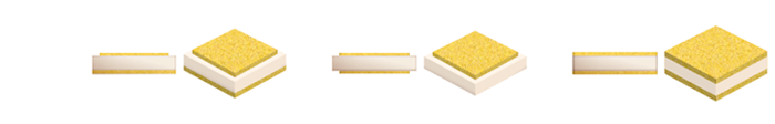
| Type A | Type B | Type C | |
| Surface | With Border | With Border | Full Metalize |
| Interior | Full Metalize | With Border | Full Metalize |
| Product | Type A | Type B | Type C |
| Single layer ceramic capacitor (Class Ⅰ & Class Ⅱ) | ◯ | ◯ | ◯ |
| Single layer ceramic capacitor (Class IV) | ◯ | ◯ | |
| Rectangular Single Layer Ceramic Capacitor | ◯ | ||
| Binary type Ceramic Capacitor | ◯ | ◯ | |
| Gap type Ceramic Capacitor | ◯ | ◯ | |
| Multi-electrode Ceramic Capacitor | ◯ | ||
| Integrated Resistor Capacitor | ◯ | ||
| Thin Film Chip Resistor | ◯ | ||
| Ground Block | ◯ |
Please contact us for custom products .
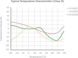
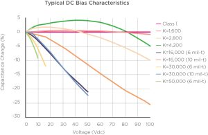
We offer a wide range of materials, from Class I to IV, so that you can select the product that best fits your specific application needs.
| EIA Class *2 |
Tecdia Dielectric Code | Dielectric Constant (Nominal Value) | Dielectric Loss @25℃ |
Insulation Resistance @25℃ |
EIA TC Code*2 |
Temperature Characteristics | Temperature Range |
| 1 | P | 40 | < 0.15% @ 1 MHz | 106MΩ | C0G | 0 ± 30 ppm / °C | -55 °C to +125 °C |
| 1 | 4 | 90 | < 0.25% @ 1 MHz | 106MΩ | S2H | -330 ± 60 ppm / °C | -55 °C to +125 °C |
| 1 | 5 | 140 | < 0.25% @ 1 MHz | 106MΩ | U2J | -750 ± 120 ppm / °C | -55 °C to +125 °C |
| 1 | 7 | 280 | < 0.25% @ 1 MHz | 105MΩ*1 | M3K | -1000 ± 250 ppm / °C | -55 °C to +125 °C |
| 2 | F | 1,600 | < 2.5% @ 1 kHz | 105MΩ | X7R | ± 15% | -55 °C to +125 °C |
| 2 | C | 2,800 | < 2.5% @ 1 kHz | 105MΩ | X7R | ± 15% | -55 °C to +125 °C |
| 2 | J | 4,200 | < 2.5% @ 1 kHz | 105MΩ | X7R | ± 15% | -55 °C to +125 °C |
| 4 | 10 | 16,000 | < 2.5% @ 1 kHz | 104MΩ | X7S | ± 22% | -55 °C to +125 °C |
| 4 | 11 | 30,000 | < 2.5% @ 1 kHz | 104MΩ | X7S | ± 22% | -55 °C to +125 °C |
| 4 | 12 | 50,000 | < 2.5% @ 1 kHz | 104MΩ | X7S | ± 22% | -55 °C to +125 °C |
*1 106MΩ@25℃ is available as a custom item.
*2 See EIA-198-1-F.
 |
|
 |
|
 |
We have three types, A, B, and C, depending on the application, and provide the optimum solution, including cost, based on the customer’s usage conditions and required specifications.
It is possible to form a AuSn film on the back side of a single layer ceramic capacitor (A type/C type). The deposition of AuSn leads to a reduction in manufacturing processes during mounting.
By not attaching Au to the back side of the single layer ceramic capacitor, the cost during epoxy mounting is reduced.
Case study page (example of high dielectric constant single layer ceramic capacitor)
In addition to the standard packing method, customization is possible.
| Material | Color | Size | |
| Waffle Pack | ABS | White / Natural | 2 inch |
| Material | Color | Size | |
| Waffle Pack* | ABC/PC/PP** | Black | 2 inch |
| Blue Tape (w/Ring) | PVC | Green | Φ 6 inch |
| Blue Tape (w/o Ring) | PVC | Green | 7.87 inch |
*Please contact us for the size of the tray.
**Conductive/Antistatic Grade
Product: European RoHS directive compliant
Packing material: European container packaging and packaging waste directive compliant
| Performance guarantee liability period | 1 year after delivery *2 | |
| Save condition*1 | Trays | Temperature +13℃~+33℃ Humidity below 60%RH |
| Tape products (excluding UV tape) | Temperature +20℃~+26℃ Humidity below 60%RH | |
*1 Avoid storage under normal pressure, direct sunlight, vibration, impact, corrosive gas atmosphere, other special gases, freezing, condensation, and dusty environments. Also, do not touch the product directly with bare hands.
*2 Tapes are guaranteed for 3 months after delivery.
When die-attaching with solder such as AuSn, we recommend products that have a barrier film of Pt or NiCr on the die-attach surface of the product.
When mounting, be careful not to short-circuit the sides due to overfilling the adhesive.
Also, cracks depend on the mounting conditions, so we recommend that you check them under your own conditions.
| ・Use Wire | Au wire less than Φ30um |
| ・Bonding temperature (supplementary matter) | Wedge bonding: 200-270°C Ball bonding: 150-250°C Tool heating is recommended. |
| ・Bonding Method | thermocompression or ultrasonic thermocompression |
| ・Notes | Bond at a distance of 25um or more from the electrode end. In addition, if the bonding acceleration is large with hard wire, it may damage the surface of the ceramic material and cause the electrode to peel off, so it is recommended to check and adjust the mounting conditions. |
 +1-408-748-0100
Office Hours: 8:30am - 5:30pm PST